(I). Mold Design Process:
Professional mold design defines every step for your custom plastic product. Good mold design avoids defects during later mold manufacturing and mass plastic production
Custom Mold Design Step‑by‑Step Workflow
Our professional mold design covers the full workflow from receiving project brief to final process document archiving. Every detail of mold design determines later mold manufacturing quality and plastic‑part production stability.
- Receive the project brief.
- Analyze the drawings: Analyze the product’s technical requirements, critical control dimensions, and tolerance requirements.
- Preliminary confirmation of the mold design: Mold structure, mold specifications, and number of cavities.
- Mold cost analysis and quotation.
- Determine the main mold structure:
(1) Cavity layout.
Determine the number of cavities and their arrangement based on the geometric characteristics of the casting, dimensional accuracy requirements, production volume, manufacturing complexity, and mold cost.
(2) Determine the parting line.
The position of the parting line should facilitate mold machining, venting, demolding, and molding operations, as well as ensure the surface quality of the die-cast part.
(3) Determine the gating system.
Confirm the shape, position, and size of the main runner, secondary runners, and gates. Also confirm the venting system, including venting method, position and size of vent channels, and arrangement of vent plates.
(4) Select the ejection method.
Choose from ejector pins, ejector sleeves, or inclined ejectors. Determine the method for handling undercuts and the core-pulling method (mechanical core pulling or hydraulic cylinder core pulling).
(5) Determine the heating and cooling methods.
Confirm the shape and location of heating and cooling channels, and the mounting locations of heating elements (oil circuits).
(6) Determine mold component dimensions.
Based on mold materials, strength calculations, or empirical data, determine the thickness and external dimensions of mold components, their external structure, and the positions of all connecting, locating, and guiding elements.
(7) Determine the structural forms of the main forming components and structural parts.
(8) Calculate working dimensions.
Consider the strength of each part of the mold and calculate the working dimensions of the forming components.
(9) Mold flow analysis.
- Draw the mold drawings.
(1). 2D mold layout drawing.
(2). Mold runner diagram.
(3). 3D mold drawings.
(4). Mold component drawings.
- Review, distribute, and archive mold drawings.
- Develop the mold machining process sequence.
- Prepare process documents (process drawings, process cards) for each process step.
- Review, distribute, and archive process documents
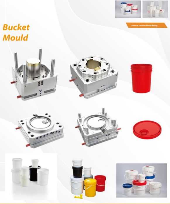
(II). Mold Manufacturing Process:
- Drawing Analysis:
(1). Analysis of product technical requirements: Focus on controlling dimensions and tolerance requirements.
(2). Review of mold assembly drawings: Review of the mold base (platen), fixed and moving core inserts, gating system, and ejection, core-pull, and cooling mechanisms.
(3) . Analysis of 3D disassembly drawings: Optimization of part machining, mold assembly, and production scheduling.
(4). Inspection of machined part drawings: Ensuring machining accuracy and dimensional compliance.
- Material Procurement: Mold base (Longji), gate sleeves, runner cones, mold inserts (DH31S), moving parts, hydraulic cylinders, ejector pins, insert pins, venting plates, etc.
- Rough Machining: Mold base (Plates A and B), gate sleeves, runner cones, mold inserts, sliding components, venting plates.
- Machining of process holes and reference surfaces; runner cones, sliding cores, inserts.
- Rough machining of ejector pin holes, wire-passing holes, and oil passage holes: mold inserts, sliding cores, inserts, gate sleeves, runner cones, and venting plates.
- Heat treatment: gate sleeves, runner cones, mold inserts, sliding cores, inserts, and venting plates.
- Finishing: Gate sleeves, runner cones (lathe, wire cutting, CNC, EDM, internal cylindrical grinding).
Mold inserts, sliding cores, inserts (wire cutting, CNC, EDM).
- Machining the ejection mechanism; rear mold insert (wire cutting for ejector pin holes, EDM for ejector pin holes to avoid clearance areas).
Mold Base B Plate (drilling of ejector pin holes).
Ejector Pin Panel (drilling of ejector pin mounting holes).
Ejector Pin Base Plate (drilling and tapping of tie-rod screw holes).
Mold Base Plate (fabrication of waste pins; drilling of ejector rod holes).
Fabrication of ejector pins, ejector pin cup head positioning, and ejector pin plate stops (grinding, machinist work).
- Machining and assembly of heating oil and cooling water channels: Gate sleeve (threaded holes machined on lathe, drill press, and tapped).
Diverting cone (threaded holes machined on drill press and tapped).
Mold inserts and sliding cores (threaded holes machined on drill press and tapped).
Mold base plates A and B (through-holes for oil channels machined on drill press).
- Machining of the pouring and venting systems: Sprue sleeves (milling machine, machining of runners).
Divergent cones (milling machine, machining of runners).
Mold inserts and sliding cores (milling machine, CNC, EDM, machining of runners, sprues, slag chambers, and vent grooves).
Vent plate (milling machine, grinding machine, CNC, EDM, wire cutting—machining vent channels and gates).
Mold base A and B plates (milling machine—machining vent grooves).
- Machining sliding components, mold alignment grooves, and mold mounting holes, etc.: Sliding components (milling machine, grinding machine, drilling machine, machinist work).
Mold stacking grooves (milled and CNC-machined).
Drilling mold holes (drilled and machined).
- Polishing of mold cores, sliding core components, inserts, insert pins, and copper pins: Rough polishing: 220# oilstone, etc.; Fine polishing: 800# to 2000# sandpaper (mirror finish).
- Part Inspection: After all parts (copper cores) for each process have been machined, they must pass inspection using measuring instruments such as a coordinate measuring machine (CMM) before proceeding to the next process.
- Mold Fitting: The mold parting line (cavity surface), sliding core sealing positions, and the mating surfaces between the gate sleeve and the runner cone are fitted by a machinist.
- Mold Assembly: Once all mold components have been machined and inspected, and all standard mold parts are in place, the mold is assembled.
- Inspect the mold and complete the “New Mold Arrival Inspection Form.”
(III). Overview of Major Mold Machining Equipment:
EDM Machines (Standard and Precision): Machining accuracy: ±0.002 mm to ±0.01 mm. Machining characteristics: Suitable for machining grooves, holes, and complex-shaped workpieces; capable of mirror-finish machining.
Milling Machine: Machining accuracy: ±0.02 mm. Machining characteristics: Suitable for machining steps, holes, shoulders, grooves, and other series of formed features.
Grinding Machine: Machining accuracy: ±0.001 mm to ±0.005 mm. Machining characteristics: Suitable for precision machining of steps, arcs, bevels, grooves, and other similar features.
Drilling Machine: Machining accuracy: ±0.02 mm. Machining characteristics: Suitable for machining holes, grooves, and other similar features.
Lathe: Machining accuracy: ±0.01 mm. Machining characteristics: Suitable for forming operations such as external circles, internal bores, and end faces, as well as roughing and finishing of various copper male inserts.
CNC Machining Center: Machining accuracy: ±0.01 mm. Machining characteristics: Suitable for roughing and finishing of fixed and moving mold bases, 3D mold cores, and various copper male inserts.
Wire EDM Machine (High-Speed and Low-Speed Wire): Machining accuracy: ±0.002 mm to ±0.005 mm. Machining characteristics: High machining accuracy, excellent surface finish, and ease of operation; capable of machining steps, holes, shoulders, grooves, and other series of forming operations.
Wire-Cut EDM Machines (High-Speed and Low-Speed Wire): Machining accuracy: ±0.002 mm to ±0.005 mm. Machining characteristics: High machining accuracy, excellent surface finish, easy operation, and capable of machining workpieces with irregular shapes on both upper and lower surfaces.
All these machining equipment work together to deliver precise mold design and reliable finished molds for our overseas customers
One thought on “Precise Mold Design: 10‑Step Complete Process for Custom Plastic Injection Molds”
Hi, this is a comment.
To get started with moderating, editing, and deleting comments, please visit the Comments screen in the dashboard.
Commenter avatars come from Gravatar.